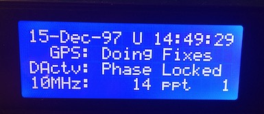
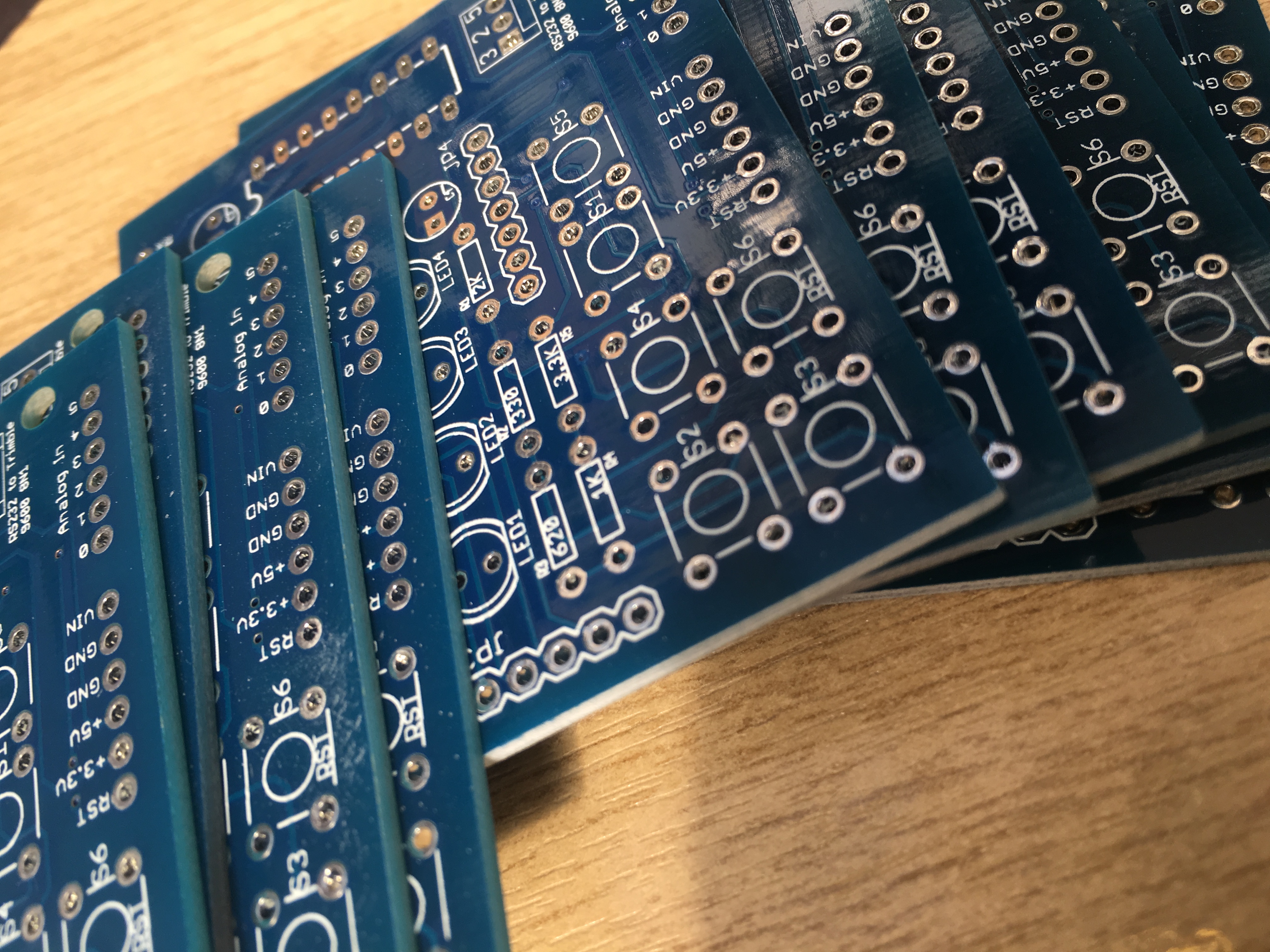
Many years ago I created a monitor for my Trimble Thunderbolt GPSDO which I use to lock my K3S and various other equipment to a solid frequency standard. Over the years there has been tremendous interest in the project as I have made the entire thing opensource. If you want to find out more then please see the following links…
- https://www.m1dst.co.uk/category/projects/trimble-thunderbolt-monitor/
- https://github.com/m1dst/Trimble-Thunderbolt-Monitor
- https://www.m1dst.co.uk/shop/
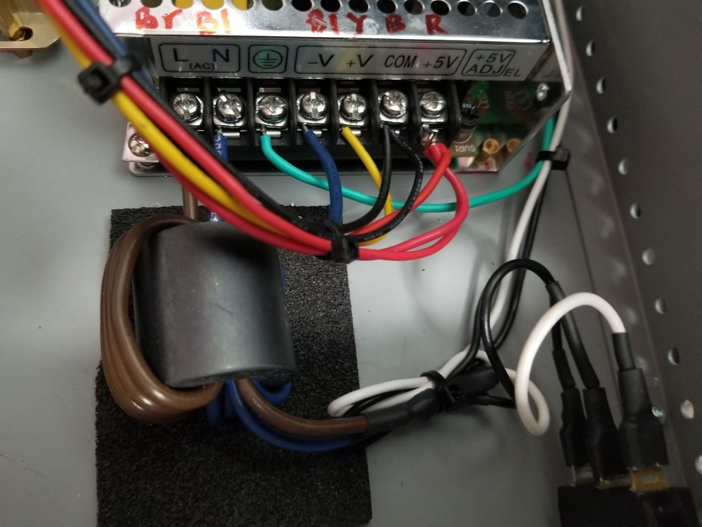
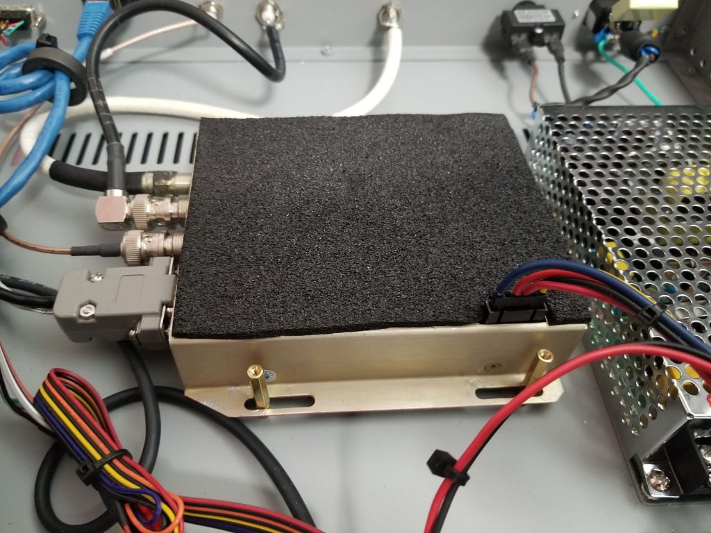
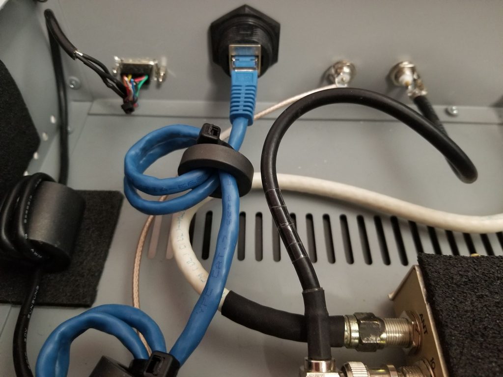
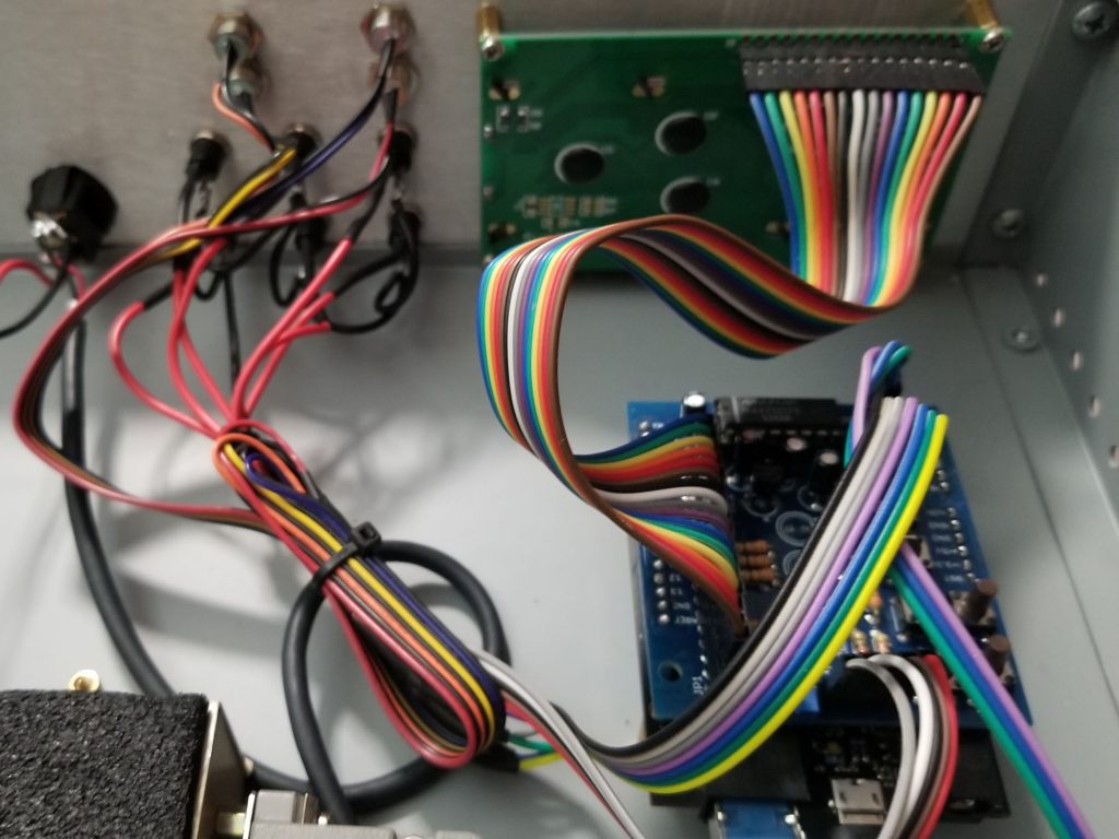
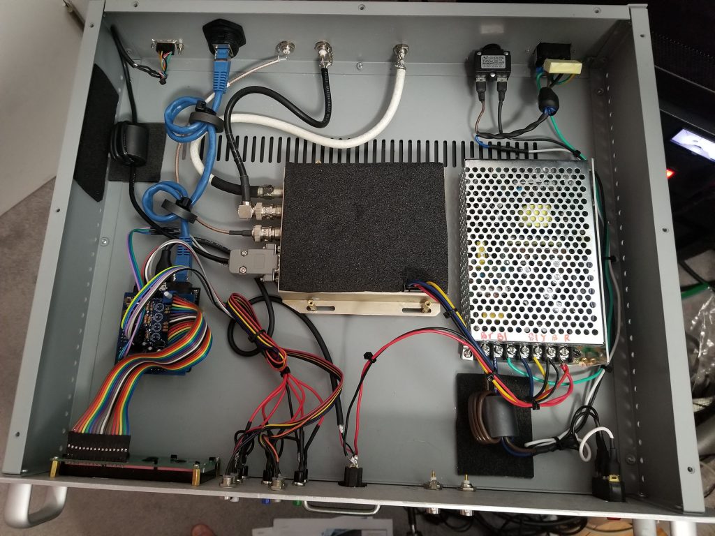
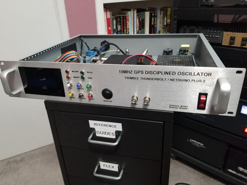
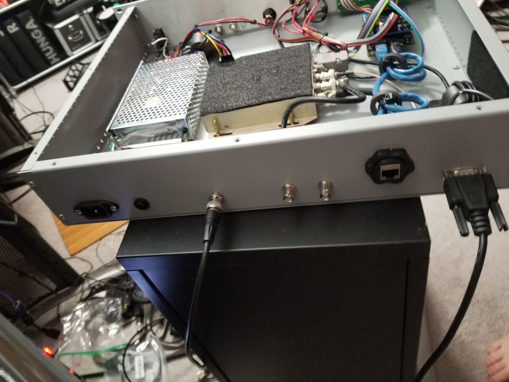
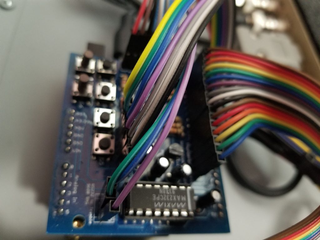
Recently I was contacted by Lucas, W6AER who had just finished building his version. He was so pleased he gave a talk to the San Francisco Radio Club. He is using his GPSDO with his Flex radio. He was kind enough to send me some photos and a link to his write up. https://w6aer.com/10mhz-gps-disciplined-oscillator-gpsdo-trimble-thunderbolt/


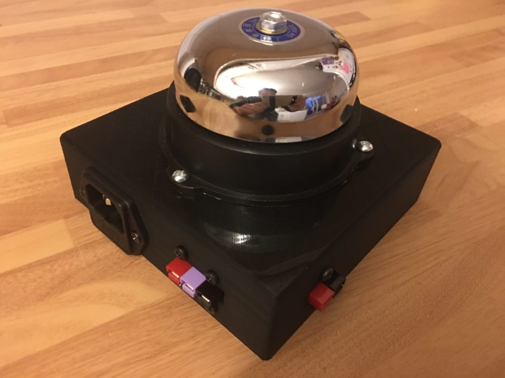
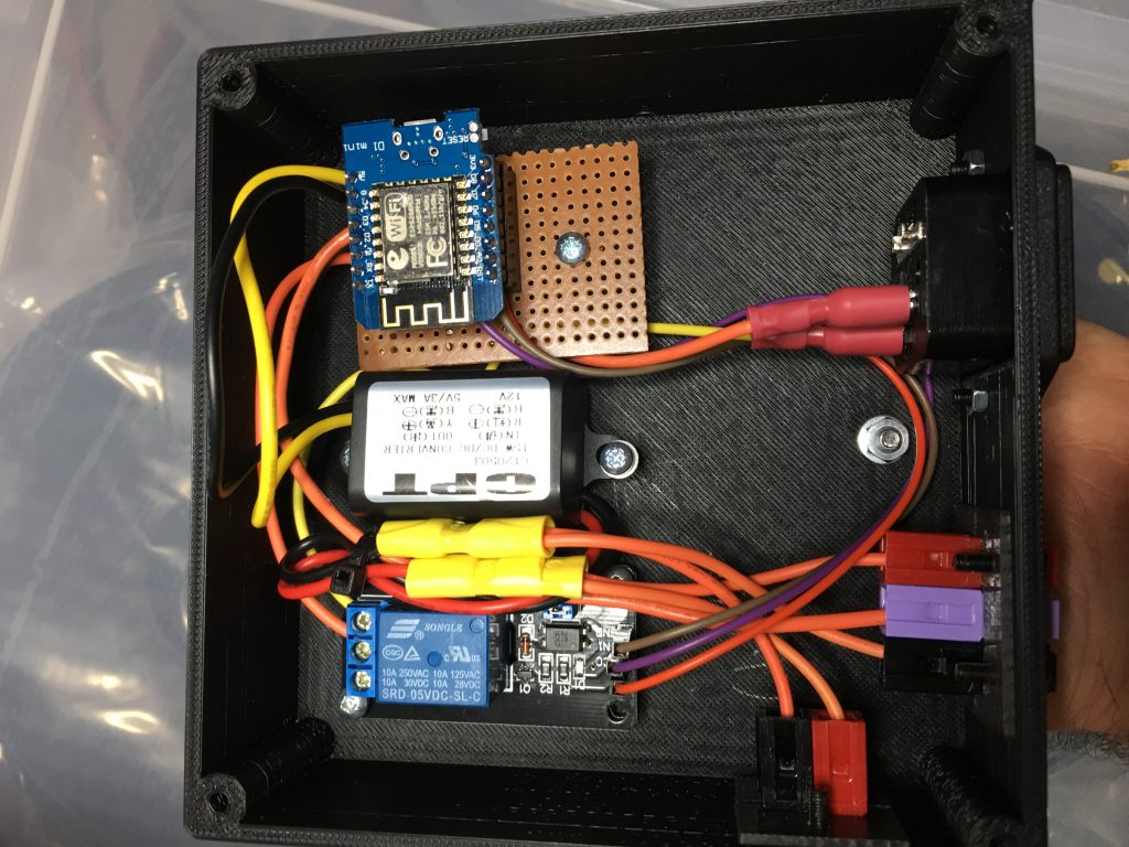
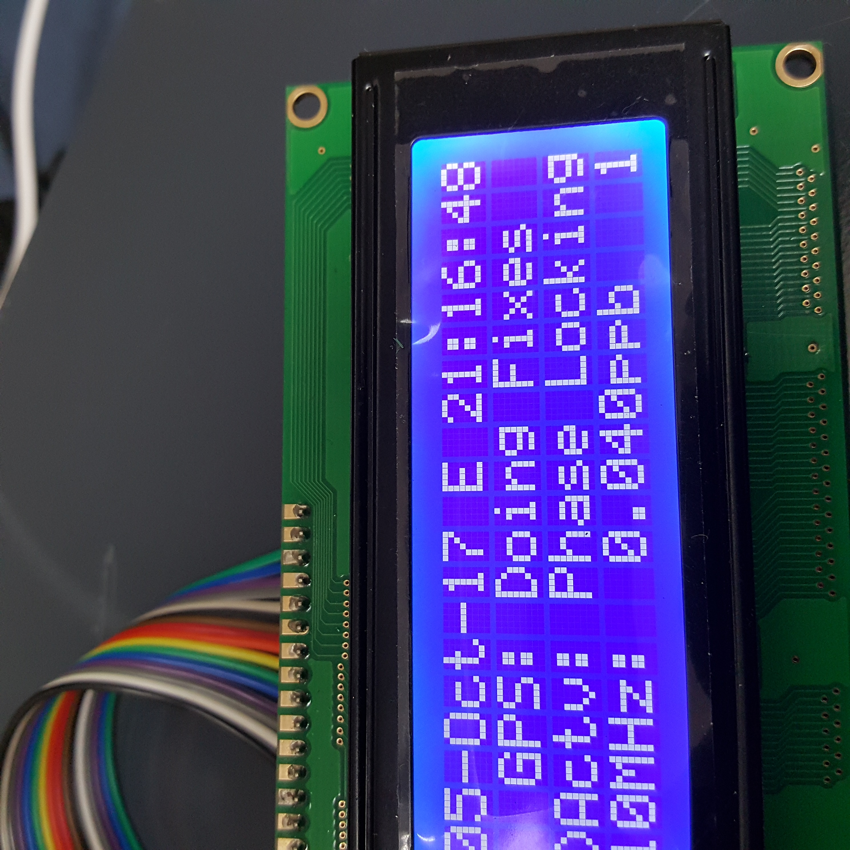
