Amateur radio, programming, electronics and other musings

Back in 2022, I started creating extensions for DXLog to do interesting things that I wanted but DXLog couldn’t or wouldn’t do. I have started contributing the code for some of the to the main code base such as the Operator and Azimuth Statistics.

I have a few others which I am integrating when I get the time but I present one which I have been using for some time which might never make the main product.

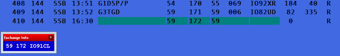
It allows you to have a new window called Exchange Info. This window shows the operator what they should be saying to the other station. It is ideal when you can’t remember your locator or you have some new operators joining you for the contest.

I think I have covered most of the dynamic data possible but if something doesn’t work right, reach out and I will attempt to fix it.

It works by parsing the contents of Message2.

You can download the latest version of the DLL at any time from https://drive.google.com/file/d/1DvHVYr3wCg41RhWDbNZbyCsHiAA2bfQJ/view?usp=drive_link

To use it, download it and copy the DLL to a folder called CustomForms (in %APPDATA%\DXLog.net folder) and restart DXLog. You may need to create the folder.

If you like it, drop me an email and let me know.

Whilst working on a port of my Thunderbolt Monitor to the ESP32 I have had to make a few simple hardware changes to the current PCB revision (v1.1). This involved remapping some IO to different pins. I blindly selected two unused pins, cut the required traces and soldered some jumper wires to make the new connections. I later found that when I placed the shield on the ESP32 it wouldn’t be detected by the flasher. If I took the shield off I could get it to appear and flash fine. This is a nightmare for testing and it didn’t take me long to look through the datasheet of the ESP32 to find out what the issue could be.

It turns out that IO12 is used during bootup. If driven High, flash voltage (VDD_SDIO) is 1.8V not default 3.3V. It has an internal pull-down, so unconnected = Low = 3.3V. It prevents flashing and/or booting if 3.3V flash is used and this pin is pulled high, causing the flash to brownout.

There are two options here. The first is to not use that pin if you can’t control the state of it during boot. The second (the option I chose) is to blow an efuse which permanently locks the state of the pin. I knew that this board would never need a 1.8V flash voltage so entered the below command and my boot issue went away.

WARNING: This is permanent. It can’t be undone.

Since I created this project more than 6 years ago it has been built by literally hundreds of people. I have made PCBs available to those that wanted them and for the hardcore builder the schematic was available and they made their own implementation on stripboard. There are a number of write-ups online about the project and even a presentation was given by someone at a convention.

Over the years I have added features for either my own requirements or others asking. This round of updates covers two distinct areas with the first relating to features.

V1.1.0

I have added four new screens which show additional information available from the Trimble Thunderbolt.

The first new screen is only available during startup and is displayed directly after the splash. You will briefly be shown the firmware and hardware versions of the connected Thunderbolt. You will also be shown the serial number. I also show the build date as it might be interesting to see how old your Trimble Thunderbolt actually is.

Screen five shows the status of each satellite, the signal strength and how many satellites are being used in a fix/tracked. The signal strength should be easy to understand. I take the reading from the Thunderbolt and map it directly to a number between 1 and 8. This draws a column chart similar to a strength meter you might find on a mobile phone interface.

Each satellite is represented with a status. The statuses I am reporting are as follows:

  • – = The default state, a placeholder if you like.
  • D = Disabled
  • F = Being used to calculate a fix.
  • A = Acquired
  • * = Reopened search
  • T = Tracked

Screen six shows the PRNs of each satellite. GPS signal consists of a navigation message and PRN codes (C/A for civil and P-code for military) which is an identity for the satellite. PRN codes are also used to determine the range between the satellite and the receiver. The navigation message added on PRN code, must be known to find the position of GPS receiver on Earth. Identification of PRN code is the most important process to calculate the receiver’s position.

Screen seven shows you further precision information. We now show PDOP, TDOP, VDOP, HDOP.

PDOP (position dilution of precision) describes error caused by the relative position of the GPS satellites. Basically, the more signals a GPS receiver can “see” (spread apart versus close together), the more precise it can be.

From the observer’s point of view, if the satellites are spread apart in the sky, then the GPS receiver has a good PDOP.

We display all the available values and give you a rough estimate as to if it is good or bad.

The code has also been refactored quite a bit to make some of it cleaner to read.

This set of updates (v1.1.0) have been made available on GitHub and will run on any of the available NETMF 4.3 boards such as Netduino. You just need to download the code, compile and deploy and you should have the new version running.

New Hardware Support, V2.0.0

I have heard a repeating thing from some builders over the years. Comments such as “I can’t find a Netduino”, “Netduinos are so expensive. Couldn’t you just rewrite this for Arduino?” I have put years of work into this project and to start again using the Arduino platform is just not an option for me.

I have however just ported the code to TinyCLR. TinyCLR OS is a modern, managed operating system that brings .NET to embedded devices. It offers garbage collection, threading, and full debugging which allows you to step through code and inspect variables. No costly debugging tools are necessary.

GHI have produced an Arduino compatible board which runs C# and only costs $10. Whilst this isn’t as cheap as the $3 Arduino clone from China, it is much cheaper than the Netduino and should hopefully reduce the barrier of entry for some people.

I purchased one of these boards and spent the day porting the code to TinyCLR rather than NETMF and have labeled it V2.0.0.

TinyCLR is used on the latest Visual Studio 2019 which is much easier for people to get installed. I might even be able to supply precompiled binaries to deploy without even having to install Visual Studio. I’ll investigate this further to see what is involved.

The features are identical to v1.1.0 except for the ability to see the uptime of the unit. I haven’t worked out how to invoke native code yet as uptime is not yet available in the managed libraries.

The other important thing to say is GHI have made TinyCLR available for a number of other boards including Netduinos. So if you have a compatible board, you could flash the bootloader and then flash the TinyCLR version of the code on.

I have not yet updated the instructions on how to flash the TinyCLR version yet, created a GitHub release or even updated the GitHub readme but I will get there eventually. Send me a pull request if you want to help.

All code is available at https://github.com/m1dst/Trimble-Thunderbolt-Monitor

This is all the news for now. If you have any thoughts, feedback or comments, send me a tweet or email.

I presented a talk on 3D printing at the upcoming RSGB Convention. It was one of the first talks on Saturday morning.

I introduced you to the fascinating world of 3D printing where you learned about the different 3D printing methods with a focus on inexpensive FDM machines. You left with an understanding of how the machine works and how 3D printing could be used as a tool to improve your Amateur Radio life. We discussed the tools used to take an idea from your head to become a finished item.

I promised to post slides to the presentation here. I have provided two files. One is just a PDF which is ideal if all you want to do is review the data tables I showed. The second file is over 100MB but contains some of the videos you were not able to see on the day.

Please feel free to send me email or tweets with any feedback.

This past weekend I decided I wanted to enter the IOTA contest. Over the years I have entered with the Swindon Radio Club but more recently we have entered as individual entries.

I decided I wanted to try something different, something hard. What could be harder than being at the bottom of the solar cycle? How about QRP? Yes.

In the UK we’ve had tremendous weather for weeks which meant it was going to be great being outside in the sun, playing radio. What could be better? Then the weather changed just before the contest started. Rain, wind and some occasional lightning.

I set myself the target of 100 QSOs but didn’t quite achieve it. Roll on next year.

Many years ago I created a monitor for my Trimble Thunderbolt GPSDO which I use to lock my K3S and various other equipment to a solid frequency standard. Over the years there has been tremendous interest in the project as I have made the entire thing opensource. If you want to find out more then please see the following links…

Recently I was contacted by Lucas, W6AER who had just finished building his version. He was so pleased he gave a talk to the San Francisco Radio Club. He is using his GPSDO with his Flex radio. He was kind enough to send me some photos and a link to his write up. https://w6aer.com/10mhz-gps-disciplined-oscillator-gpsdo-trimble-thunderbolt/

The MFJ-269 suffers from being accidentally switched on when in the box. Newer models have had a switch guard added as standard. I don’t actually like the design of the official MFJ improvement on the 269B as I find it hard to switch on.

My 269 is not the B revision and required improving to ensure it could only be switched on when required. I designed two different guards.  One is solid and hides the screw heads, the other looks nicer.

The STL files are available here and on Thingiverse.