Amateur radio, programming, electronics and other musings

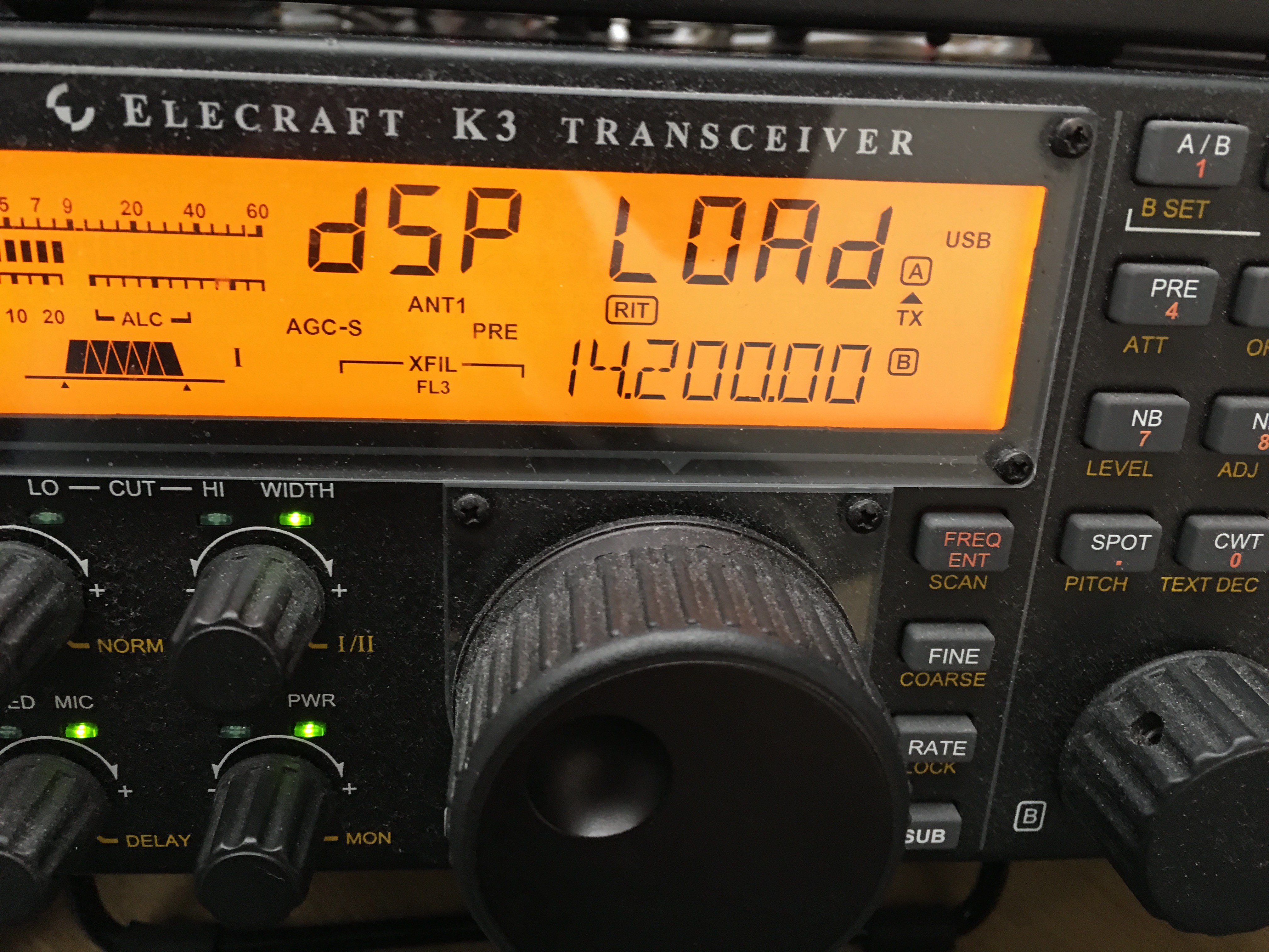
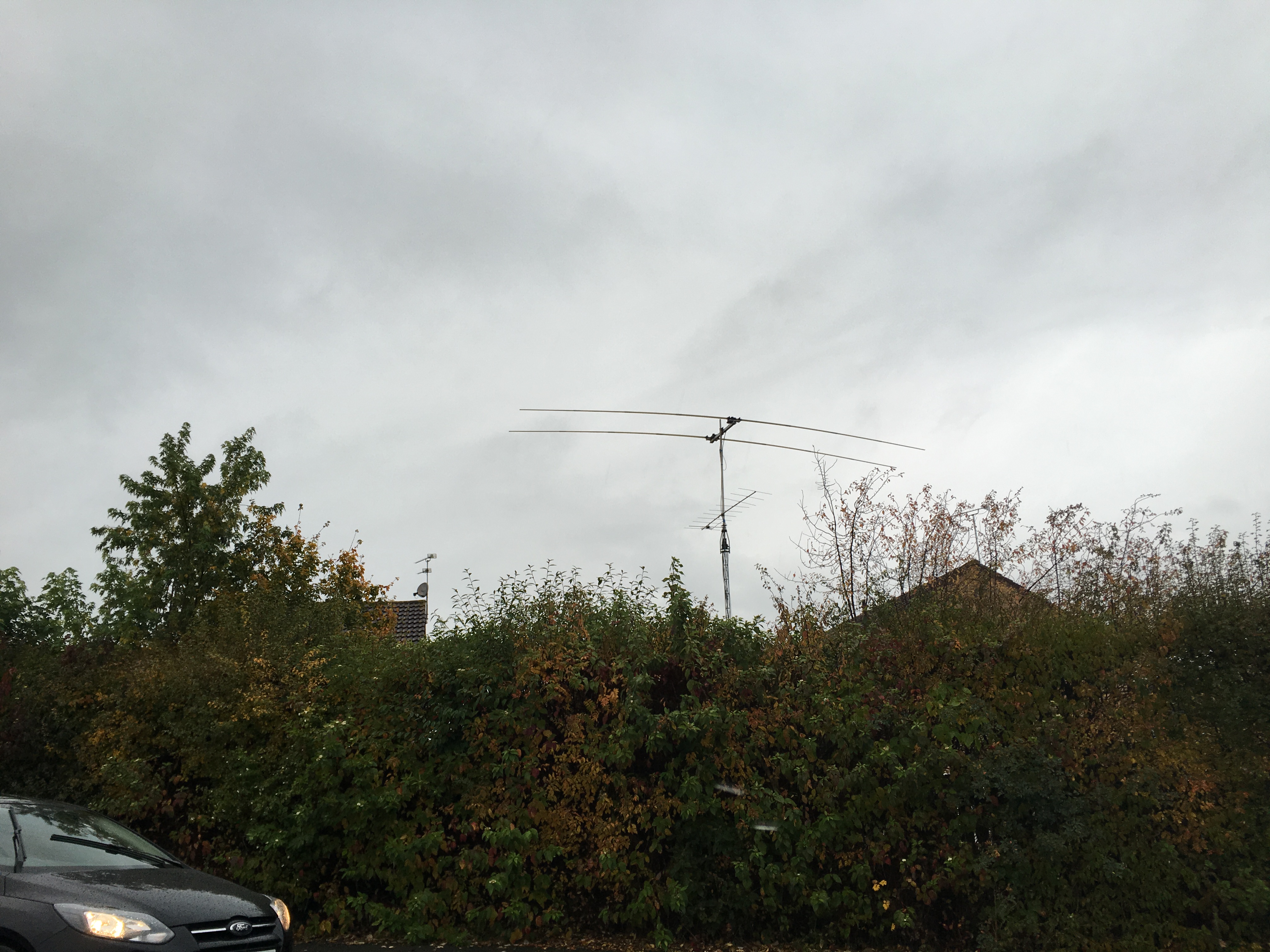
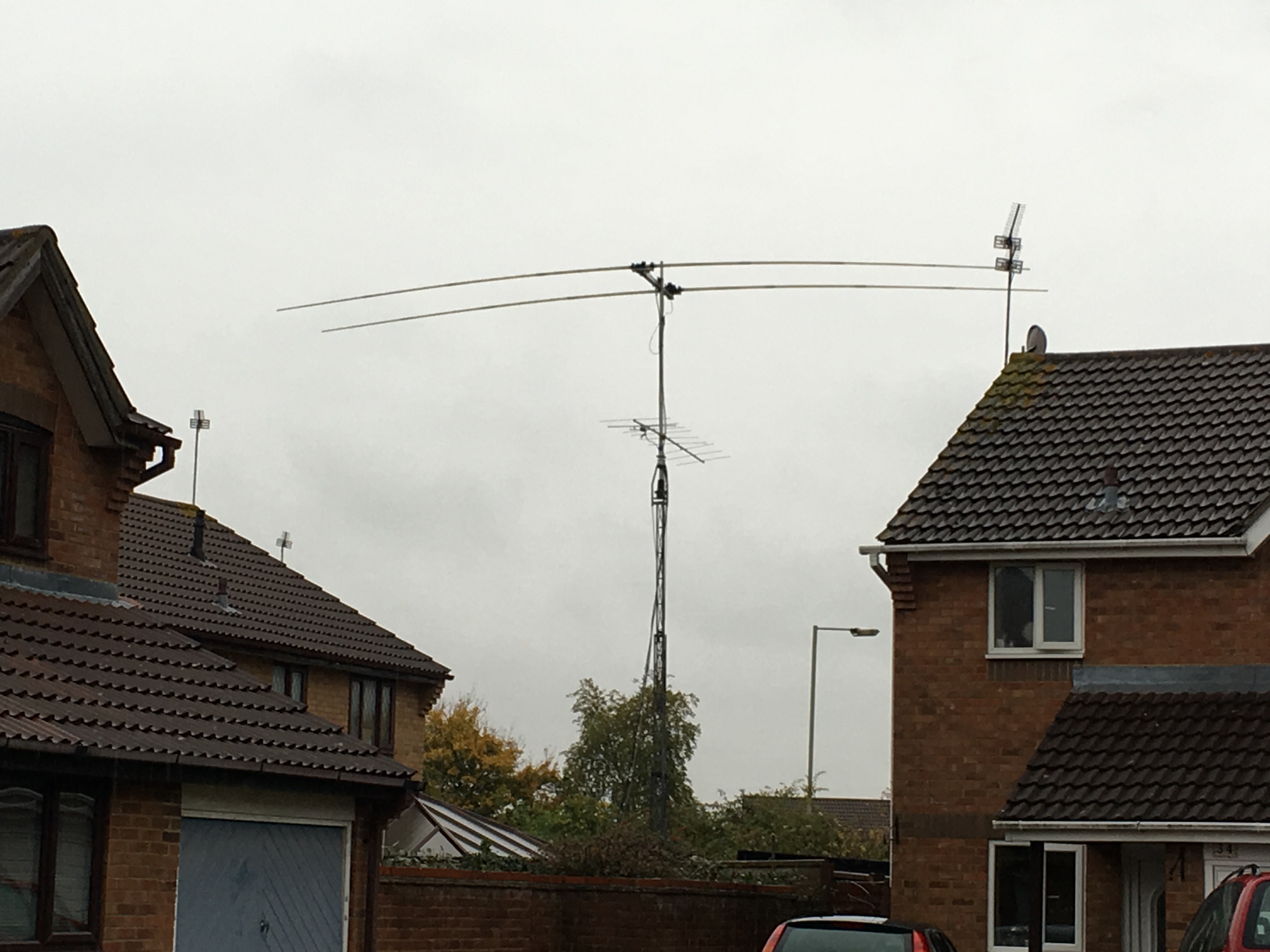
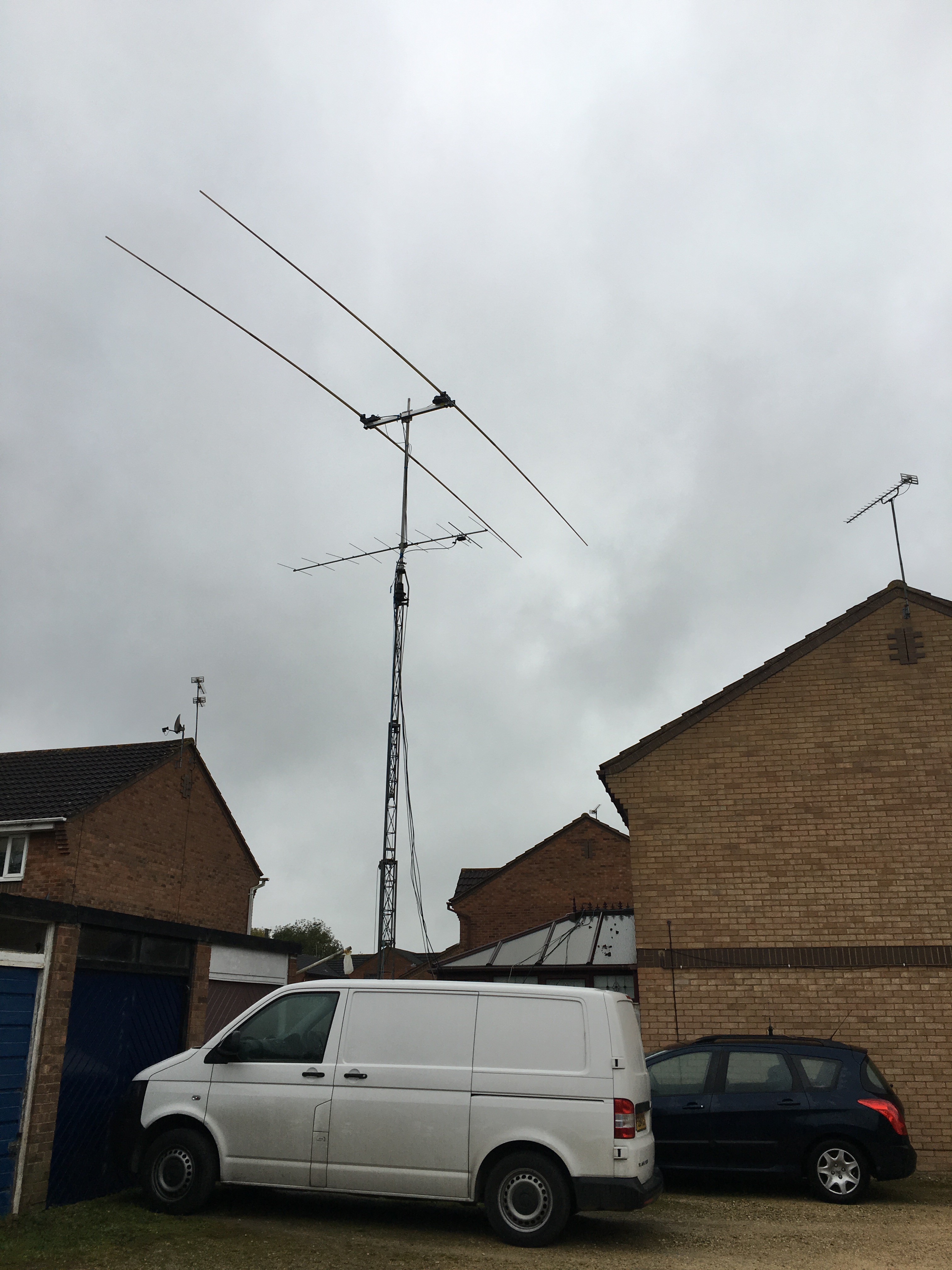
This weekend I switched on the K3S and operated in the CQWW SSB contest. It wasn’t a serious entry as family life still needs to continue. Sam managed to keep the kids safe, fed and entertained for most of the time allowing me to operate. I had a couple of technical issues at the start of the contst. My Ultrabeam was showing a high SWR which almost stopped me taking part at all. In the end, I remembered there is a calibration routine built into the controller. Once I recalibrated the antenna all was well. The other issue is RS232 stopped working around the time I was fixing the antenna. This turned out to be a hardware fault. I hadn’t screwed the DB9 into the back of the P3 and it had fallen out. Doh! Fixed and no more issues.

My target was at least 400 QSOs, 55K points, 20 Zones and 80 DXCC. I didn’t reach the zone or DXCC targets this time. I made 3 QSOs as a result of a CQ call and the rest were all S&P.

Contest         : CQ World Wide DX Contest
Callsign        : M1N
Mode            : PHONE
Category        : Single Operator - Assisted (SOA)
Overlay         : ---
Band(s)         : Single band (SB) 20 m
Class           : Low Power (LP)
Zone/State/...  : 14
Locator         : IO91CN
Operating time  : 12h15

 BAND   QSO  CQ DXC DUP  POINTS   AVG 
--------------------------------------
  160     0   0   0   0       0  0.00 
   80     0   0   0   0       0  0.00 
   40     0   0   0   0       0  0.00 
   20   400  18  78   0     577  1.44 
   15     0   0   0   0       0  0.00 
   10     0   0   0   0       0  0.00 
--------------------------------------
TOTAL   400  18  78   0     577  1.44 
======================================
         TOTAL SCORE : 55 392

Dupes are not included in QSO counts neither avg calculations

Operators       : M1DST
Soapbox         : A fun but not serious entry.

Many contest groups around the world use a hotel/butler bell to indicate a multiplier has just been worked. Jeeves is a modern, automated replacement for the bell which can be installed in or away from the working area. It also doubles up as 12v lighting for the area.

When a QSO is logged, a packet is broadcast from N1MM+ which Jeeves captures and inspects. Depending on the multiplier status of the QSO, the LED string changes colour and dances to match the 8 possible states. This is ideal for contest sites where the communal area is away from the working area and a bell may not be heard. It allows the non operators the fun of keeping track on the progress of the contest. A bell also sounds for 25ms.

My installation now requires no setup for a contest other than plugging into a 12v source (and mains if the bell is to sound).

Hardware

  • ESP8266 – I used a WeMos D1 Mini ~ £3.50
  • 5V Relay Module ~ £2.50
  • 5M string of WS2812 LEDs (300) (12v) ~ £15
  • 5V DC/DC to power the ESP from 12V
  • Small plastic enclosure – I designed and 3D printed mine including the powerpole clamps. STL available if requested.
  • Smoothing Capacitor – Connect a big capacitor from power to ground (LEDs). A cap between 100µF and 1000µF should be OK.
  • Mains powered bell – a 12V bell is more ideal but I couldn’t find one at a reasonable price. ~ £9.00

It might be possible to use one of the ESP8266 boards available with a built in relay if you can ensure that you can access spare IO pins to run the LEDs.

It is important to use 12v LEDs and power them directly. You will not be able to power these from the ESP device. Also, consider that you can use even longer runs of LEDs by purchasing another string and plugging it into the end of the original. The only thing to consider is the volt drop so be prepared to feed 12v directly into each string. If you don’t then you will find the LEDs may sparkle or not show the colour you are expecting.

Setup

  • Download the code from https://github.com/m1dst/Jeeves
  • Set your SSID and password by changing the const values.
  • Change LED_COUNT to match the number LEDs in your string.
  • Validate that the data pins in the config represent the pins you are connecting to.
  • If you DO NOT want the lights to indicate a non mult QSO was logged, comment out the DISPLAY_EVERY_QSO definition at the top of the sketch.

Video

Future Expansion Ideas

  • Sniff the current score broadcasts and perhaps expose to a responsive web interface.
  • Perhaps post a message to an MQTT queue for further processing.
  • The default state of the LED string is white which is perfect for lighting in a tent. Lighting may not be required during the day. Perhaps use NTP to work out the time of the day and hardcoded/GeoIP to determine the rough location or country.
    With this information, it would be possible to calculate sunrise/sunset and set the brightness accordingly.
    There is no point in white lights showing during a bright sunny day consuming energy.
  • Win-Test – Not currently possible to check multiplier status due to the limited information Win-Test broadcasts via UDP. QSO logged and status should be possible though.

I received an email from someone in the US who had just built one of my Thunderbolt Monitors. He casually asked if there was a way of showing EST rather than UTC on the display. Whilst on a computer this would be easy, it is a little harder on NETMF due to the fact it doesn’t understand timezones. It isn’t just a case of subtracting 5 hours from the UTC time as we also need to consider daylight savings time.

After some research, I put together a code change which appears to work for him and should handle the daylight savings rules too. Before I share the code I must warn you that this is a little rough but solves the problem. I will not be releasing this in the main branch but you should be able to hack it in if you really want it.

Add the following to the end of the class of program.cs.

public static bool IsDaylightSaving(DateTime dt)
{
    var dow = (int)(dt.DayOfWeek);

    // January, February, and December are out.
    if (dt.Month < 3 || dt.Month > 11) { return false; }

    // April to October are in
    if (dt.Month > 3 && dt.Month < 11) { return true; }

    var previousSunday = dt.Day - dow;

    if (dt.Month == 3 && dt.Day >= 8 && dt.Day <= 14 && dow == 0)
    {
        return dt.Hour >= 2;
    }

    // In March, we are DST if our previous sunday was on or after the 8th.
    if (dt.Month == 3) { return previousSunday >= 8; }

    if (dt.Month == 11 && dt.Day >= 1 && dt.Day <= 7 && dow == 0)
    {
        return dt.Hour >= 2;
    }

    // In November we must be before the first Sunday to be DST.
    // That means the previous Sunday must be before the 1st.
    return previousSunday <= 0;

}
 
public static DateTime ConvertToEasternTime(DateTime dt)
{
    var utcOffsetHours = -5;
    if (IsDaylightSaving(dt))
    {
        utcOffsetHours += 1;
    }
    return dt.AddHours(utcOffsetHours);
}

Change references of :

string mode = _thunderbolt.TimingMode == TimingModes.UTC ? "U" : "G";
_lcdshield.WriteLine(0, DateTime.UtcNow.ToString(@"dd-MMM-yy " + mode + " HH:mm:ss"));

to

string mode = "E";
_lcdshield.WriteLine(0, ConvertToEasternTime(DateTime.UtcNow).ToString(@"dd-MMM-yy " + mode + " HH:mm:ss"));

I changed the U/G to an E to signify Eastern time but feel free to ignore that or even replace it with just a space instead.

A number of people have had trouble sourcing the Netduino boards and asked me for help. I have now added support for the GHI FEZ Lemur board which is a perfect replacement for the Netduino devices. They seem to be in stock from places like Mouser which is also handy.

In theory, we should be able to get this working on any pin similar board such as the GHI Panda III or Cobra III etc. If you have a board you need support for, let me know and I’ll roll out a new project. I have simplified the projects to use shared files and ifdefs so it is quite quick.

See: https://github.com/m1dst/Trimble-Thunderbolt-Monitor

For the PCB see https://www.m1dst.co.uk/shop/

I’ve had an MFJ-269B for many years.  It is a useful tool to have when building and testing antennas prior to putting them into service.  It runs from 12v and allows you to fill it with 10AA batteries.  I filled it with 3000mAh batteries.  The problem I found was it always seemed like the analyser was out of charge.  The analyser contains a charge circuit and if the jumper is in the “charge” position the batteries are charged when plugged into an external 12v source.

Looking at the schematic it shows that the charge circuit is only capable of providing 69mA at best.  I’ve heard others indicated it could be as low as 20mA.   This means the charge time could be anywhere from 2-7 days!  Not useful at all.

I decided to pull out the batteries and replace with a LiPo battery.  I took some measurements of the available space and went hunting for a suitable battery from HobbyKing.  Once the battery arrived I took some photos of the mods to share here.

The process was as simple as this….

  1. Remove the rear casing (8 screws)
  2. Remove the battery holder (2 screws)
  3. Snip the wire off of the battery holder and terminate it with either a JST or PowerPole.  I use PowerPoles on EVERYTHING.
  4. Cut some cardboard to provide some insulation between the battery and the PCB.  It will also ensure that anything sharp won’t pierce the battery.
  5. Ensure that the “charge” jumper is not enabled.
  6. Ensure the battery is fully charged.
  7. Mate the two power connectors
  8. Place the battery into the analyser
  9. Replace the back cover
  10. Check the analyser is still working.

I may install a panel mount PowerPole and balance cable so that I don’t have to remove the back cover to charge the battery.  The LiPo lasts far longer than the batteries and can be charged extremely quickly when it does go flat.

You may find your Trimble Thunderbolt Monitor is showing the incorrect date at the moment.  It could be showing the year as 1997.  This is due to the date in the Thunderbolt being reported incorrectly.

GPS Time is a continuous counting time scale beginning at the January 5, 1980 to January 6, 1980 midnight. It is split into two parts: a time of week measured in seconds from midnight Sat/Sun and a week number. The time of week is transmitted in an unambiguous manner by the satellites, but only the bottom 10 bits of the week number are transmitted. This means that a receiver will see a week number count that goes up steadily until it reaches 1023 after which it will “roll over” back to zero, before steadily going up again. Such a week rollover will occur approx. every 20 years. The last week rollover occurred in 1999 and the next one will be in 2019.

The Thunderbolt manual states…

The ThunderBolt adjusts for this week rollover by adding 1024 to any week number reported by GPS which is less than week number 936 which began on December 14, 1997. With this technique, the ThunderBolt will provide an accurate translation of GPS week number and TOW to time and date until July 30, 2017.

The Thunderbolt can now not be trusted to give the accurate date and time and the responsibility of the time correction has now been forced onto the hardware/software which is reading data from the Thunderbolt.  I have written a fix and released v1.0.4 which attempts to correct the time.  Please visit https://github.com/m1dst/Trimble-Thunderbolt-Monitor and download the latest version.  Give it a try and report back any issues.

It is very likely I will have to patch again when the GPS system rolls its week over on April 6th 2019.

Contest : IOTA Contest
Callsign : M1N
Mode : PHONE
Category : Single Operator – Assisted (SOA)
Band(s) : All bands (AB)
Class : Low Power (LP)
IOTA : EU005
Operating time : 11h55


BAND QSO DUP IOTA POINTS AVG
80 0 0 0 0 0.0
40 0 0 0 0 0.0
20 148 1 46 1350 9.12
15 78 0 25 720 9.23
10 6 0 4 70 11.67
TOTAL 232 1 75 2140 9.22

TOTAL SCORE : 160,500

Dupes are not included in QSO counts neither avg calculations

Operators : M1DST
Soapbox :

Suffered with wideband noise at various times during the contest on Sunday and had a headset mic element fail which needed repairing.  Should have considered entering unassisted as I almost never used the cluster.

Today I noticed two WordPress sites I maintain had some broken images. I keep all of my images in Azure Blob Storage so I jumped into Cloudberry Explorer and looked at the files contained in the blob container. I found my images were there. I looked at the source of the page and noticed that the markup has changed for some images.

Since WP4.4 it appears that responsive images have been implemented. The markup for an image now looked like…

&lt;img class="alignright size-medium wp-image-8931" src="http://m1dst.blob.core.windows.net/blog-media/2014/09/lipo-dist-clean-angled-300x300.jpg" sizes="(max-width: 300px) 100vw, 300px" srcset="https://m1dst.blob.core.windows.net/blog-media/2014/09/lipo-dist-clean-angled-150x150.jpg 150w, https://m1dst.blob.core.windows.net/blog-media/2014/09/lipo-dist-clean-angled-300x300.jpg 300w, https://m1dst.blob.core.windows.net/blog-media/2014/09/lipo-dist-clean-angled-1024x1024.jpg 1024w, https://m1dst.blob.core.windows.net/blog-media/2014/09/lipo-dist-clean-angled-144x144.jpg 144w, https://m1dst.blob.core.windows.net/blog-media/2014/09/lipo-dist-clean-angled-480x480.jpg 480w, https://m1dst.blob.core.windows.net/blog-media/2014/09/lipo-dist-clean-angled-900x900.jpg 900w, https://m1dst.blob.core.windows.net/blog-media/2014/09/lipo-dist-clean-angled-924x924.jpg 924w" alt="lipo-dist-clean-angled" width="300" height="300" /&gt;

The code above is the fixed markup not the code that was failing. Having looked in Developer Tools I noticed I was getting a 404 on an image load. Looking at where the image was coming from showed it wasn’t from Azure. This meant that the Azure Storage plugin didn’t yet know about the new SRCSET property. Some searching online found a number of people experiencing the issue and various fixes. http://projectnami.org/fix-for-azure-storage-plugin-and-wp-4-4/ is the blog post that helped me fix my problem.

Hopefully Microsoft will release an official plugin update soon.  UPDATE: The plugin has been updated and this fix is no longer required.

Further Reading

Contest : CQ World Wide DX Contest
Callsign : M1N
Mode : PHONE
Category : Single Operator – Assisted (SOA)
Overlay :
Band(s) : Single band (SB) 20m
Class : High Power (HP)
Zone/State/… : 14
Operating time : 18h30


BAND QSO CQ DXC DUP POINTS AVG
80 0 0 0 0 0 0.0
40 0 0 0 0 0 0.0
20 620 25 93 6 1017 1.64
15 0 0 0 0 0 0.0
10 0 0 0 0 0 0.0
TOTAL 620 25 93 6 1017 1.64

TOTAL SCORE : 120,006

Dupes are not included in QSO counts neither avg calculations

Operators : M1DST
Soapbox :

A few of us from the Swindon Radio Club each entered CQWW in various sections. So we could each follow progress we submitted our realtime scores to http://cqcontest.net/ which was great fun to watch.

Had some issues with RF killing the Universal Serial Bus (USB) which broke CAT, keyboard and mouse control making logging difficult in the first few minutes. This was quickly solved with a single ferrite.

I decided to “fiddle” during the contest with Win-Test scripts. I wanted to allow PTT from the keyboard instead of using the footswitch. I did this using a modified script and the pause button. If I press the pause button then it toggles the PTT. I can also use ESC to always kill the PTT regardless. I was using the internal voice keyer on the K3 using the F1 – F3 keys on the keyboard.

Had plenty of fun but as usual family needed attention so time was limited. I should have spent more time calling CQ and less time getting distracted on webpages, within apps etc. There is always next year.

Oh and whilst tinkering I also reloaded the K3 firmware in the hope that my scripts would work properly. The problem was F1 would trigger the CQ and ESC would stop it. If the CQ was in repeat mode, the ESC wouldn’t cancel it. Very odd. I found a bug in the script which I fixed but it still didn’t work properly even if triggered from the radio. A firmware updated fixed the problem. Phew.

Uploaded log to CQWW, LOTW, ClubLog, my Log, and [email protected]. Also submitted claimed score to 3830.